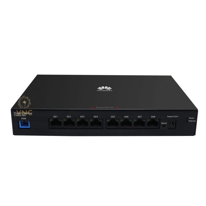
Huawei OptiXstar F200D-8G
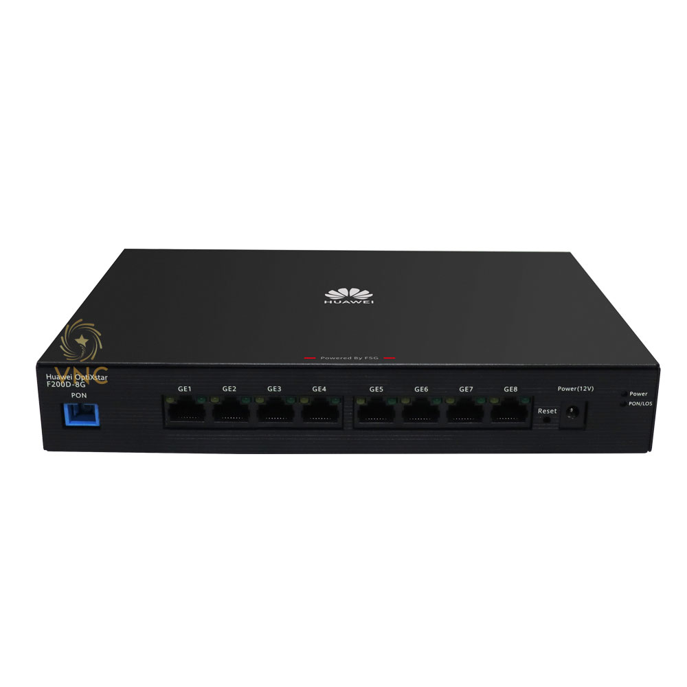
Device Appearance

The figures shown in this document may differ from the actual products, but the differences do not affect the functions of the products.
|
Port/Button |
Description |
|---|---|
|
PON |
Connects to an SC/UPC optical connector to support GPON upstream transmission. |
|
GE1–GE8 |
Works as Ethernet ports and supports 10 Mbit/s, 100 Mbit/s, or 1000 Mbit/s autonegotiation. |
|
Power |
Connects to a power cable. |
|
Reset |
Resets the device. Press and hold the button for less than 10 seconds and release it to restart the device, or press and hold the button for longer than 10s to restore factory settings. NOTE:
Exercise caution when restoring the device to factory settings. After the device is restored to factory settings, it may fail to access the Internet. If a device cannot access the Internet after being restored to factory settings, contact the service provider for help. |
Typical Application
As a box-shaped ONU, the F200D-8G supports MiniFTTO and FTTO networking scenarios.


Device Installation

- Huawei OptiXstar F200D-8G is an optical network terminal. F200D-8G is also called ONU for short.
- Do not stack ONUs that are placed horizontally.
- Do not expose the device outdoors.
- It is recommended that adapters and fibers not be vertically installed above ONUs.
- Use the standard power adapter provided by Huawei to supply power to the device. Otherwise, the device may not work properly or security risks may be introduced.
- Do not route Ethernet cables or adapter cables outside a network box.
- Install the device in a confined area, such as a network box. Only professional personnel are allowed to operate and maintain the device.
- The device can be used indoors or outdoors. When used outdoors, the device must be installed in a network box, cables must be routed in a secure way, and an outdoor surge protective device (SPD) must be installed at the power port to prevent lighting strikes from damaging the device. Suggestions for installing an SPD:
- It is recommended that a Huawei-certified SPD be installed at the power port of the network box. The ground cable of the SPD should be security connected and as short as possible (length < 20 cm and diameter > 6 mm2). The key specifications requirements are as follows:
- Surge specifications: 20 kA in differential and common mode
- Maximum continuous operating voltage: 385 V AC
- Voltage protection level: 1.8 kV
- Other layout and grounding requirements for the SPD in the network box:
- Impedance requirements: The impedance between the ground bar of the network box and the ground is less than 10 ohms, and the impedance between the SPD and the ground bar is less than 0.1 ohm.
- Cable length requirements: To ensure that the network box is reliably grounded, the ground cable of the network box should be shorter than 30 m. It is recommended that a cable longer than 5 m be coiled to connect the power SPD and the ONU power port.
- Layout requirements: A power SPD (able to withstand 20 kV lightning strike) is installed close to the ONU between the circuit breaker and ONU power socket. Ensure that the distance between the AC power cable and network cable is longer than 50 cm. Keep the network cable as short as possible and do not route the excessive network cable in parallel with the AC power cable (recommended length of parallel routing < 50 cm).
- Other specifications (including waterproof, temperature, and humidity requirements) are consistent with those for other ONU products.
- It is recommended that a Huawei-certified SPD be installed at the power port of the network box. The ground cable of the SPD should be security connected and as short as possible (length < 20 cm and diameter > 6 mm2). The key specifications requirements are as follows:
Space for Heat Dissipation

- The space requirements for heat dissipation indicated in the following figures are applicable to ONUs desktop flat, wall-mounted and network box installation.
- The heat dissipation sides are not allowed to have any contact with the wall or desktop.
Horizontally Placed on a Desktop

Do not stack products that are placed horizontally on a desktop.
Mounting on the wall (1)
It is recommended that the port be facing down to prevent other objects such as dust from falling in for wall mounting, as shown in the following figure.
- Mark two positions with the same spacing as that between the two mounting holes of the ONU using a marker on a wall.
- Select a proper drill bit according to the outer diameter of the screws. Use a hammer drill to drill the marked positions on the wall. Then clean the holes and install two expansion bolts.
It is recommended that the screw diameter be less than or equal to 4 mm, the nut diameter be 6 to 8 mm, and the length should not be less than 20 mm.
- Use a screwdriver to fasten the screws into the expansion bolts, reserving 5 mm ends out of the wall, and mount the ONU onto the screws.
Mounting in the network box

- Do not use an enclosed network box and ensure that the air intake and exhaust vents are not blocked to ensure proper heat dissipation of the ONU.
- If the network box is installed indoors or in a corridor that is free from rain, the network box must meet the requirements of IP31 protection. (“IP” is short for international protection. The first number indicates a class for preventing the solid particle from entering the device and the second number indicates a class for preventing water from entering the network box. “3” means that solid particles with diameters equal to or larger than 2.5 mm can be prevented from entering the box. “1” means that the drips fallen vertically cannot damage the device.)
- If the network box is installed outdoors or in a corridor that is exposed to rain, the network box must meet the requirements of IP55 protection. (“5” means that the network box cannot completely prevent dust from entering, but the amount of dust that enters the network box does not damage the device. “5” means that the water sprayed from different directions to the network box does not damage the device.)
- The method for installing the ONU in a non-Huawei network box depends on the network box specifications. When the ONU is installed in a non-Huawei network box, the preceding heat dissipation space rules must be observed.
- Guide for Grounding the Network Box of TN-S and TN-C-S Power Distribution Systems
- In the case of the TN-C-S and TN-S AC power distribution systems, you are advised to use the PE wire of the AC power cable for the ONU grounding connection. The PE wire of the AC power cable for the corridor of the building is already grounded properly.
- Connect the ground bar and all the internal devices using the ground cable (the cross-sectional area of the ground cable must be greater than or equal to 6 mm2), and the ground bar to the network box in an equipotential manner through a metallic structure.
- Connect the grounding point of the strength member of the optical fiber to the ground bar through a ground cable, or connect this grounding point to the network box in an equipotential manner through a metallic structure.
- When the PE line of the AC power cable in the corridor of the building does not meet the grounding requirement, ground the network box through an external ground cable (PGND cable) and ensure that the strength member of the optical fiber is disconnected from the device ground point.
- Decouple the surge protector from the ONU power source using a power cable of 3–5 m.
- Guide for Grounding the Network Box of the TT Power Distribution System
- In the case of the TT power distribution system, you are advised to use an external ground device. For example, use a grounding device dedicated for buildings (such as the ground flat steel, ground stud, and ground bar) or the base steel bar of the reinforcement concrete of the building, or deploy a new ground grid.
- Use the ground cable (the cross-sectional area of the ground cable must be greater than or equal to 6 mm2) to connect the ground bar and all the internal devices, and the ground bar to the network box in an equipotential manner through a metallic structure.
- Connect the external ground cable (PGND cable) of the network box to the external ground device. As specified by the grounding standard, the cross-sectional area of the external ground cable must be greater than or equal to 16 mm2.
- Guide to Ground the Strength Member
Table 3-1 Engineering Responsibilities
Optical
Cable Provider
Engineering Party
Recommended Solution
Remarks
Huawei
Huawei
Solution 1 is preferred. If solution 1 fails to implement, Huawei is required to communicate with the customer about engineering risks and sign a memorandum with the customer before using solution 2.
If solution 1 is used, the engineering quality must strictly comply with engineering specifications. If solution 2 is used, the network box must be securely grounded. In addition, a metal protective cover must be installed between the fiber strength member and network box fixing points, preventing sparks from spreading if the fiber strength member connects to a heavy-current power line.
Customer
Solution 1
If the engineering does not comply with solution 1, the customer must take consequences.
Customer
Huawei
Requirements: During engineering, do not route the fiber strength member into the network box. In addition, ground the fiber strength member and the network box separately. Install the network box and ONU based on the instructions provided in this document.
The customer must ensure that the fiber strength member is not be routed inside the network box. Otherwise, the customer must take consequences.
- Grounding solution 1: The fiber strength member is isolated from the network box and grounded outside the network box.
This solution prevents the introduction of sudden heavy currents into the network box, thereby protecting the device inside the network box against heavy currents. (A long-distance armored optical cable may introduce sudden heavy currents into the network box if the outer insulation layer is broken and connects to a heavy-current power line.) Solution 1 is implemented as follows:
- Strip the outer insulation layer and armored tube from the fiber strength member at the ground point. Then, clean bare optical fibers and use a protection tube to protect them. (Use outdoor tubes in outdoor scenarios and common tubes in indoor or corridor scenarios. Use waterproof tape produced by 3M or COTRAN.)
- Use a piece of sandpaper to polish burrs at the stripped position of the optical cable. Then, use insulation tape to wrap the stripped optical cable. When wrapping the waterproof tape, ensure that fiber cores are force-free.
- Cut excess fiber strength member for grounding.
- During onsite operations, ensure that optical fibers are force-free and the bend radius is greater than 40 mm. Otherwise, services may become abnormal or even fail due to degraded signal transmission.
- The fiber strength member must be securely grounded. In addition, the ground point of the fiber strength member must be at least 3 meters above the ground (which prevents manual touching), and no combustible materials are around the ground point within a distance of 0.3 m. If the fiber strength member fails to be securely grounded, it must be insulated. Otherwise, the fiber strength member may introduce heavy currents if it connects to a heavy-current power line, threatening human safety.
- Grounding solution 2: The fiber strength member is grounded inside a network box.
The fiber strength member must be connected to a ground bar at the ground point using a ground cable. The ground point can connect to the network box using a metal in an equipotential manner. When the fiber strength member connects to a heavy-current power line, heavy currents may be discharged inside the network box using the ground bar. If this happens, sparks may occur at the contact point between the fiber strength member and the ground bar, which may burn the device and the network box. To prevent this issue from occurring, use solution 1.
If the ground bar of the network cabinet fails to securely ground, ensure that the fiber strength member is disconnected from the ground bar and that the fiber strength member is properly insulated. Otherwise, heavy currents may be discharged using the network ports on the local and peer devices, which may damage these network ports.
- Grounding solution 1: The fiber strength member is isolated from the network box and grounded outside the network box.
Cable Connections

- The fiber connector type is SC/UPC and the color is blue. Do not use other types of connectors. Otherwise, the optical power may be abnormal.
- The preceding figures are for reference only.
Indicator Information
|
Indicator |
Color |
Status |
Description |
|---|---|---|---|
|
POWER |
Green |
Steady on |
The device is powered on. |
|
Off |
The device is powered off. |
||
|
PON/LOS |
Green |
Blinking rapidly (twice per second) |
The PON port is connecting to the upper-layer device. |
|
Steady on |
The PON port is connected to the upper-layer device. |
||
|
Red |
Blinking slowly (once every 2 seconds) |
The PON port is not connected with a fiber or has no optical signal. |
|
|
Steady on |
The PON port is prohibited by the upper-layer device or sends optical signals abnormally. Contact the service provider for help. |
||
|
Yellow |
Blinking slowly (once every 2 seconds) |
The hardware of the terminal connected to the PON port is faulty. |
|
|
GE1–GE8 |
Green |
Steady on |
The Ethernet connection is normal. |
|
Blinking |
The Ethernet port is transmitting or receiving data. |
||
|
Off |
The Ethernet connection is not set up. |
Technical Specifications
|
Item |
Specifications |
|---|---|
|
Dimensions (H x W x D) |
220 mm x 150 mm x 35 mm (excluding rubber pad) |
|
System power supply |
12 V DC, 1 A |
|
Power adapter input |
100–240 V AC, 50/60 Hz |
|
Operating temperature |
–10°C to +55°C |
|
Operating humidity |
5% to 95%, non-condensing |
|
Weight |
About 1.2 kg |
|
Static power consumption |
5 W |
|
Maximum power consumption |
8 W |

 Hotline: 0911658758


https://glassiuk.Wordpress.com/ –
I got this ste from my buddy who informed me about this website andd now this time I am bdowsing
this web page and reading very informative articles or reviews at this time. https://glassiuk.Wordpress.com/
https://izibiz.pl/companies/tonebet-casino/ –
I was curious if you ever thought of changing thee layout of your website?
Its very well written; I love what youve got to say.
But maybe you could a little more in the way of content so people could connect
with it better. Youve got an awful lot of texzt for only having 1 orr two pictures.
Maybe you could space it out better? https://izibiz.pl/companies/tonebet-casino/