
 Hotline: 0911658758


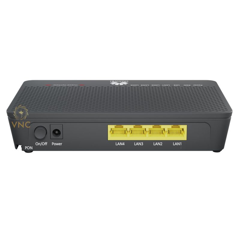
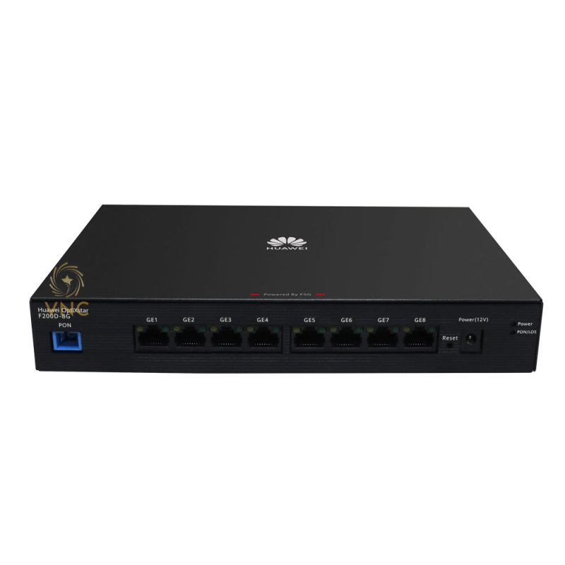
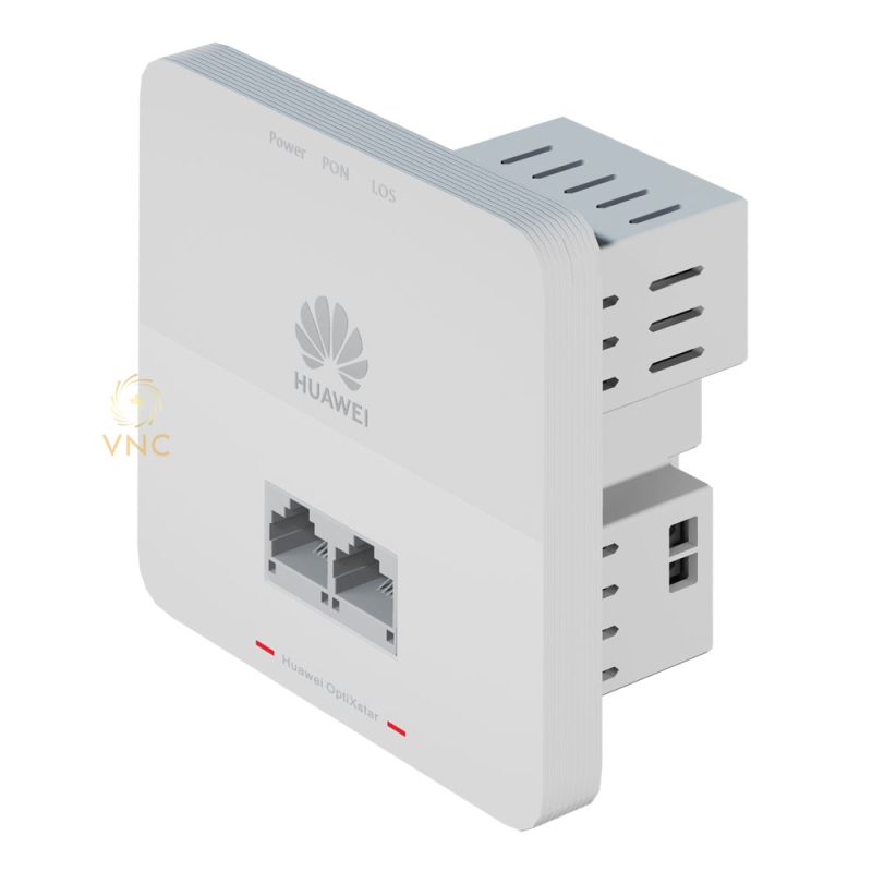
Huawei OptiXstar F100P-2G
Product Appearance
Huawei OptiXstar F100P-2G product is a panel ONU for enterprise campus networks.


Rear view


If the appearance of the product in this document differs from the actual product, the actual product prevails.
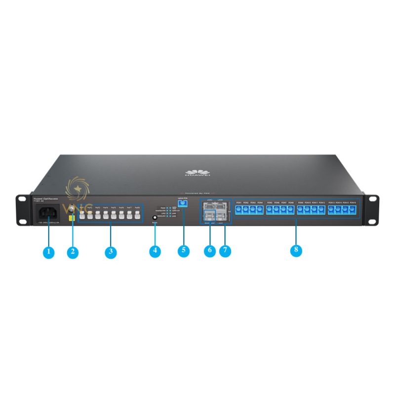
|
No. |
Ports, buttons, and indicators |
Description |
|---|---|---|
|
1 |
Indicators |
The options include Power, PON, and LOS. For details, see 6. |
|
2 |
Reset button |
Press and hold down the button for 10 seconds to release the button to restart the system. Press and hold for more than 10 seconds to restore the factory settings. NOTE:
The button is located under the device housing. NOTE:
Exercise caution when using the reset button. After the device is restored to its factory settings, the Internet may not be accessed. If you cannot access the Internet after restoring factory settings, contact your service provider. |
|
3 |
Indicator switch |
Used to turn on and off the indicator. Press the key for more than 3 seconds. NOTE:
The button is located under the device housing. |
|
4 |
GE port |
Two GE Ethernet ports, which are connected to computers, IP STBs, or cameras. The port rate is auto-sensing at 10 Mbit/s, 100 Mbit/s, or 1000 Mbit/s. |
|
5 |
Optical fiber interface |
The interface type is SC/UPC. |
|
6 |
Live wire connector (L) and neutral wire connector (N) |
Connect the fire wire and the neutral wire and connect the power supply. |
|
Name |
Specifications |
Quantity |
|---|---|---|
|
Crimping terminal of the AC power cable |
/ |
2 |
|
Screw |
M4×25 |
2 |
Typical Application
As a box-shaped ONU, the device supports MiniFTTO and FTTO networking scenarios.


Installing the Device

- Install the equipment only by professional personnel. Do not install the equipment without permission.
- For your safety, install a disconnecting device that is accessible to the outside of the product. The disconnecting device and the product must be installed by professional personnel, and installation and disassembly are not allowed. Also, be sure to disconnect the power supply before installation and removal by professional personnel.
- Before installation, disconnect the power supply and ask professionals to lead out the cables from the wall in the 86 type electric box. Keep a certain distance between the cables to avoid contact with each other.
- Do not use detergents, gasoline, ammonia or other corrosive chemicals to wipe the product.
- This product is only suitable for installation on concrete or non-flammable surfaces.
- During the installation, use protective terminals to protect the optical fiber to avoid contamination on the end face of the optical fiber.
- The tools and auxiliary materials that are not delivered with the equipment must be prepared by professional personnel.
Select suitable 86 electric box and drop cable
The panel ONU is applicable to hotels, hotels, and families. For different household types, the product can be matched according to the needs.
- Please use an international standard 86 electric box for installation. The depth must be greater than 50 mm to meet the coiling of redundant cables.
- Before installation, ensure that the drop cable with a 0.9 mm loose fiber and a 0.9 mm diameter SC/UPC short tail fiber (recommended BOM code: 14130631) are used.
- The drop cables and pigtails must be connected by hot melt. The length of the hot melt protection tube should not exceed 4 cm.
- Do not use cold connection terminals for the drop cable and pigtail to avoid fiber coiling due to insufficient space.
- It is recommended that 0.5 m of drop cables be reserved to ensure that there is still room after two hot melts.


F100P-2G
The F100P-2G panel ONU can be easily and quickly mounted in a Type 86 electrician box inside the wall.
- Connect the neutral wire and the live wire to the neutral wire inlet N and the live wire inlet L respectively, and tighten the screws on the side.
- Make sure to confirm the zero and fire wires before connecting them to avoid reverse connection.
- To ensure safety, it is recommended that you use the crimping terminals in the auxiliary material package to crimp the zero and live wires and then install them. For details about how to crimp an AC power cable, see A.
The preceding figure is only a schematic diagram, and the actual figure may prevail.
- Insert the spliced optical fiber plug in the 86 type electric box into the corresponding optical fiber interface of the equipment, and place the equipment into the 86 type electric box inside the wall.
- When coiling a 0.9 mm pigtail, exercise caution to avoid bending and damage. It is recommended to coil the fiber at the back of the box and fix it with tape, then put it into the 86 type electric box, or use a small inner diameter winding pipe for protection.
- During construction, coil the incoming cable and part of the pigtail along the inner diameter of the 86 box, and fix it with adhesive tape to avoid loosening.
- Disassemble the panel, align the screw holes on the equipment and the 86 electric box, and install screws to fix it. Do not over tighten the screws.
- Fix the panel and complete the installation.


Connecting Cables

Description of Indicator
|
Indicators |
Status |
Description |
|---|---|---|
|
Power |
Always on |
Power ON |
|
extinguished |
Power Off |
|
|
PON |
as shown in Table 6-2 |
|
|
LOS |
as shown in Table 6-2 |
|
The status of PON and LOS reflects the connection between ONU and the optical line terminal (OLT). The following table describes the status of the PON and LOS LEDs.
|
Status Number |
Indicator Status |
Description |
|
|
PON |
LOS |
||
|
1 |
Flashing twice per second |
extinguished |
The ONU is connecting to the upper-layer device. |
|
2 |
Always on |
extinguished |
The ONU is connected to the upper-layer device. |
|
3 |
extinguished |
Blinking slowly (1 time/2 seconds) |
The ONU is not connected to an optical fiber or has no optical signal. |
|
4 |
extinguished |
Always on |
The ONU is disabled by the upper-layer device or is abnormal. Contact the service provider. |
|
5 |
Blinking slowly (1 time/2 seconds) |
Blinking slowly (1 time/2 seconds) |
ONU hardware fault |
Technical Specifications
|
Item |
Specifications |
|---|---|
|
Dimensions (W x H x D) |
Panel: 86 mm x 86 mm x 10 mm Internal module depth: 35 mm |
|
Weight (excluding power adapter) |
168g |
|
Power input |
F100P-2G: 100-240V AC, 50/60Hz |
|
Maximum power consumption |
7.2W |
|
Operating ambient temperature |
-5℃ – +40℃ |
|
Operating ambient humidity |
5% to 95%, non-condensing |
|
Application Scenarios |
Indoor |
https://fortune-glassi.mystrikingly.com/ –
Outstanding story there. What happened after?
Thanks! https://fortune-glassi.mystrikingly.com/