
 Hotline: 0911658758


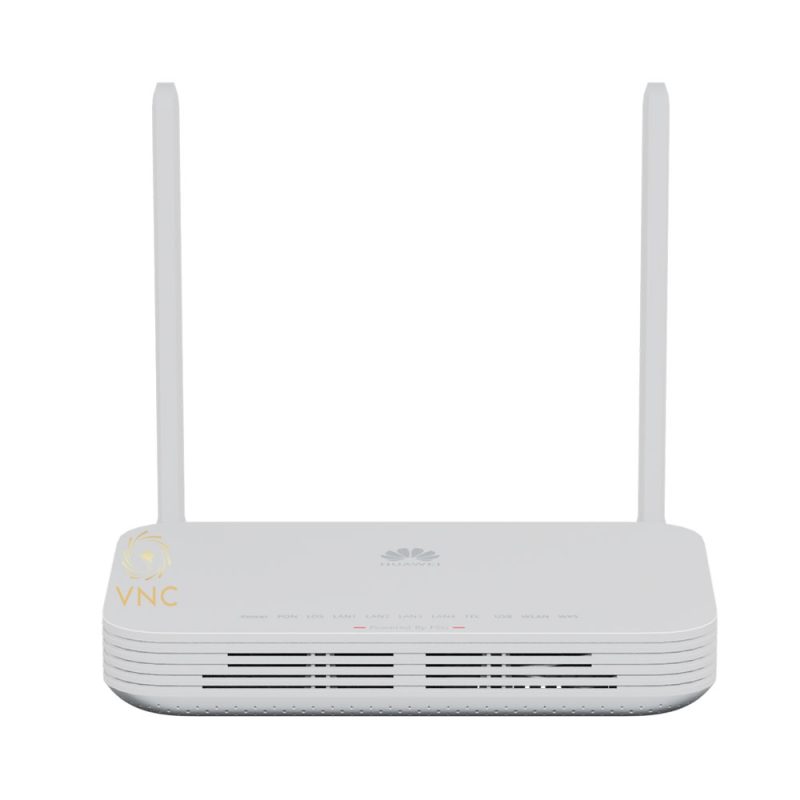
Huawei OptiXstar F1001-AC
Device Appearance


The schematic diagram in this document may differ from the actual product of the OptiXaccess F1001-AC (F1001-AC or primary gateway for short).
|
Interface Type |
Interface silkscreen |
Interface Description |
|---|---|---|
|
AC power connector |
-100-240V;50/60Hz;2.0A |
Connects to the 100 V/240 V AC power supply. |
|
Grounding point |
|
Used for grounding equipment. |
|
Downstream optical interface |
PoF 1-8 |
Provides eight XC/UPC ports. The built-in optical/electrical composite cable power adapter is connected to the optical/electrical composite cable to supply power to the downstream ONU and transmit optical signals. NOTE:
PoF refers to the optical/electrical composite cable with an output voltage of 56 V. Pay attention to safety. |
|
Reset key |
Reset |
NOTE:
|
|
Upstream optical port |
Uplink-PON |
Supports XG-PON upstream transmission. |
|
Uplink GE port |
WAN/LAN1 |
Supports Ethernet GE upstream transmission. |
|
Downlink GE interface |
WAN/LAN1-LAN4 |
Connects to a computer, IP STB, or router, and supports auto-sensing of the 10 Mbit/s, 100 Mbit/s, or 1000 Mbit/s interface rate. The WAN/LAN1 port can be used as the WAN port. |
|
Downstream optical interface |
PON1-16 |
Provides 16 SC/UPC interfaces to implement downstream access with ONUs. |

The following figure shows the small all-optical networking of Huawei MiniFTTO.
- The primary gateway F1001-AC connects to the downstream ONU through the PoF (optical-electrical composite cable) and supplies power to the remote ONU. A maximum of eight ONUs can be connected.
- The primary gateway F1001-AC connects to the downstream ONUs through a leather cable. A maximum of 16 ONUs can be connected.

Installation of equipment
The F1001-AC can be installed horizontally on an indoor desktop, in a 19-inch cabinet, or in a network box.

- All diagrams in this document may be different from the actual product. These differences do not affect the product functions.
- In the following, F1001-AC is referred to as a primary gateway.
- Do not stack primary gateways in horizontal deployment mode.
- To ensure proper grounding of the equipment, it is recommended that the grounding cable be operated by professionals.
Flat desktop
Do not stack the tabletop when it is placed horizontally. Ensure that the device is properly grounded before powering on.

Installing a 19-inch Cabinet
Install mounting ears when installing the cabinet, as shown in the following figure.
- Do not stack the devices in the cabinet. Ensure that the devices are properly grounded before powering on the cabinet.
- For better heat dissipation, it is recommended that the top of the device be spaced at least 88.9 mm (1 U = 44.45 mm, 88.9 mm (2 U), the bottom of the device be at least 44.45 mm (1 U), and the front of the device be spaced at least 70 mm.

Installation in a Network Box
- Do not install an ONU in an enclosed network box and verify that the air intake and exhaust vents are not blocked to ensure proper heat dissipation.
- A network box installed indoors or in a corridor free from rain must reach the IP31 protection level. Digit 3 means foreign matters with a diameter of 2.5 mm or larger cannot enter the box, and digit 1 means vertical water drops will not cause damages to the device).
- A network box installed outdoors or in a corridor exposed to rain must reach the IP55 protection level. The first digit 5 indicates the protection level against solid foreign matters, meaning that dust that enters the box will not cause damages to devices inside. The second digit 5 indicates the protection level against water, meaning that water ejected from every direction onto the box will not cause damages to devices inside.
- The method for installing an ONU in a non-Huawei network box varies with the network box specifications, but the preceding space requirements for heat dissipation must be observed.
- Guide to grounding the network box of the TN-S and TN-C-S power distribution systems
- For the TN-C-S and TN-S AC power distribution systems, it is recommended that the PE wire of the AC power cable be used to ground the ONU. The prerequisite is that the PE wire of the AC power cable for the corridor is already grounded properly.
- Verify that all devices in the network box are connected to the ground bar by ground cables (with a cross-sectional area of at least 6 mm2), and that the ground bar is equipotentially connected to the network box by a metal structure.
- Connect the grounding point of the fiber strength members to the ground bar using a ground cable, or connect the grounding point to the network box in an equipotential manner using a metal structure.
- If the PE wire of the AC power cable of the corridor is not properly grounded, the network box must be grounded using an external ground cable (PGND cable). In addition, the fiber strength member must be disconnected from the device grounding system.
- Connect a power cable of 3–5 m between the SPD and the ONU power supply for decoupling.

- Guide to grounding the network box of the TT power distribution system
- In the case of the TT power distribution system, it is recommended that an external grounding device be adopted. For example, use the dedicated grounding device of the building (ground flat steel, ground rod, or ground bar), use steel ribs in the concrete base, or deploy a new ground grid.
- Verify that all devices in the network box are connected to the ground bar by ground cables (with a cross-sectional area of at least 6 mm2), and that the ground bar is equipotentially connected to the network box by a metal structure.
- Connect the external ground cable (PGND cable) of the network box to an external grounding device. The cross-sectional area of the external ground cable must be equal to or greater than 16 mm2 (subject to the national standards of countries).

- Guide to grounding the fiber strength member of the network box provided by the customer
Table 2-1 Engineering responsibilities
Optical Cable Provider
Construction Owner
Recommended Method
Remarks
Huawei
Huawei
Method 1 is preferred. If method 1 cannot be implemented, communicate with the customer about engineering risks and sign a memorandum with the customer before using method 2.
If method 1 is used, the engineering quality must strictly comply with engineering specifications.
If method 2 is used, the network box must be securely grounded. In addition, a metal protective cover must be installed between the fiber strength member and network box fixing points to prevent fire from spreading if a fiber strength member contacts a heavy-current power line.
Customer
Method 1
If the engineering does not comply with method 1, the customer bears the responsibility for risks.
Customer
Huawei
Requirements: During engineering, do not route fiber strength members into the network box. Ground the fiber strength members and the network box separately. Install the network box and ONU according to the installation guide in this document.
The customer must ensure that the fiber strength members are not routed into the network box. Otherwise, the customer bears the responsibility for risks.
- Grounding method 1: Fiber strength members are isolated from a network box and grounded outside the network box separately.
This method prevents the introduction of sudden heavy currents into the network box, thereby protecting the device inside the network box. (A long-distance armored optical cable may introduce sudden heavy currents into the network box if the outer insulation layer is broken and any metal part contacts a heavy-current power line.) Method 1 is implemented as follows:
- Strip the outer insulation layer and armored tube from the fiber strength members at the ground point. Then, clean bare fibers and use a bare fiber protection tube to protect them. (In outdoor scenarios, use an outdoor tube. In indoor or corridor scenarios, use a common tube. It is recommended that you use 3M or KeChuang waterproof tape.)
- Use sandpaper to remove burrs at optical cable stripping points, and wrap the stripping points properly with waterproof tape. When wrapping waterproof tape, ensure that the fiber cores are not squeezed.
- Cut excessive fiber strength members and reserve a proper length for grounding.
- During onsite operations, ensure that fibers are free from stress and the bending radius is greater than 40 mm. Otherwise, services may become abnormal or even fail due to degraded signal transmission.
- Fiber strength members must be securely grounded. A ground point must be at least 3 meters above the ground to avoid accidental touching, and must be free from combustible materials within 0.3 m. If fiber strength members cannot be grounded, take proper insulation measures; otherwise, electric shocks may occur if the fiber strength members contact heavy-current power lines.
- Grounding method 2: Fiber strength members are grounded inside a network box.
Connect the grounding point of the fiber strength members to the ground bar using a ground cable, or connect the grounding point to the network box in an equipotential manner using a metal structure. If a fiber strength member contacts a heavy-current power line, the current is discharged through the ground point in the network box into the earth. In this case, the contact point between the strength member and the ground bar may catch fire and damage devices inside the network box. Therefore, grounding method 1 is recommended.
If the ground bar of the network box cannot be securely grounded, ensure that the fiber strength members are disconnected from the ground bar and properly insulated. Otherwise, strong currents may be discharged through network ports on the local and peer devices, which may damage these network ports.
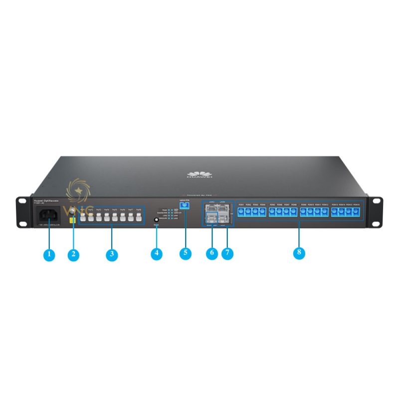
Cable Connection
Figure 3-1 F1001-AC cable connection
Table 3-1 Cable ConnectionNo.
Interface
Description
1
AC power connector
Connect the AC power cable.
2
grounding point
Connect the PGND cable.
CAUTION:Properly connecting the PGND cable ensures the lightning protection and interference protection of the chassis. Ensure that the device is securely grounded. Otherwise, the device may be damaged by lightning stroke, service exceptions, and personal safety risks.
3
Downstream optical interface
The XC/UPC interface is connected to the downstream ONU through an optical/electrical composite cable.
Connection to optical splitter is not supported.
4
Upstream optical port
SC/UPC port, used to connect to the uplink optical fiber.
NOTE:Before connecting the upstream optical fiber, check whether the optical power of the upstream optical fiber is within the range of –8 dBm to –28 dBm.
5
Uplink GE port
Connect the uplink network cable.
6
Downlink GE port
Connects to a computer, IP STB, or router, and provides an adaptive Ethernet access rate of 10 Mbit/s, 100 Mbit/s, or 1000 Mbit/s. To connect to an external network, insert the WAN/LAN1 port.
7
Downstream optical interface
SC/UPC interface, connected to the downstream ONU through optical fibers.
Connection to optical splitter is not supported.
Indicator Description
Indicators
Status
Description
Power
Green indicator is always on
Indicates that the power supply is working properly.
Blinking green (1s on and 1s off)
Indicates that the downstream PoF port has no power output.
Off
Indicates that the power supply is off or faulty.
Uplink-LOS
Blinking red
Indicates that the receive optical power is lower than the optical receiver sensitivity.
Off
Indicates that the receive optical power is normal or the upstream optical port is not connected.
Uplink-PON
Green indicator is always on
Indicates that the device has been activated.
Blinking green
Indicates that the device is being activated.
Off
Indicates that the device is not activated or the upstream optical port is not connected.
Downlink-PON
Green indicator is always on
The corresponding PON port has ONUs online or services running.
Off
No ONU is online at the corresponding PON port.
WAN/LAN1-LAN4
Green indicator steady on
Indicates that the port is connected.
extinguished
Indicates that the port is not connected.
Technical Specification
Project
Specifications
Dimensions (W x D x H)
442 mm x 245 mm x 43.6 mm
Weight
3.0 kg
AC power supply
100 ~ 240V AC, 50/60 Hz
Operating ambient temperature
-10°C – +40°C
Operating ambient humidity
5% RH to 95% RH, noncondensing
- Grounding method 1: Fiber strength members are isolated from a network box and grounded outside the network box separately.


https://Glassi-Greyhounds.mystrikingly.com –
You’re so cool! I don’t believe I’ve truly read something like this before.So wonderful to find somebody with original thhoughts on this
topic. Seriously.. many thanks for starting this up.This website is one
tbing that is needed on the internet, someone with a little originality! https://Glassi-Greyhounds.mystrikingly.com